STEM Coding – Simple codes

Today, I went onto code.org. I signed up to a class pin which will help my app developing skills. In the lesson I finished the coding lesson 4 and 5 and are half way through 6.

Some of the challenges I encountered were not having a turn right block which I could use. As a compromise I used 3 turn lefts then later, when I learned about making and defining functions, I made a function called turn right which has 3 turn left block. This will make it easier for me to turn right as if I need to, I can just use that function as a shortcut.

Functions are coding blocks that you can define to make your code more efficient. For example the turn right function that I created saved me from using the turn left block 3 times. This is a new skill that I learned today.

I also learned that you cannot duplicate a block. To solve this problem, I changed the code from block to text and copied and pasted the code I needed more than once. This saved time and helped this time be more efficient.

Today I learned about how much you can do with a limited amount of blocks. When I was coding, the only blocks I were given were:

penUp

penDown

moveForward

turnLeft

I also learned that small errors can change the whole code. An example of this is when my friend told me that her code was not working as she programmed the turtle to do a function 4 times, but the code only worked 3 times. I then pointed out that she forgot the brackets after her function name.

At the moment I am really excited to see what I will be learning next.

With my solar power traffic lights. I did some research on Monday. I found out that they did exist but they were not common in the world. I also found a list of solar power objects and this helped me understand how common they are in the world.

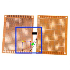
So far, I have found some videos on YouTube about circuits and how to DIY build a traffic light. With DIY build a traffic light video, I am instead planning on attaching the wires to the solar panels instead of the battery. I was also brainstorming ideas of the shape of the traffic light, I thought that it would be good to build it out of a non flammable material to ensure the safety of overheating. I am thinking of not building it out of wood, but maybe 3D print it. I’m not exactly sure what shape the final product will turn up as so I am trying to be flexible. I am aiming to go for a simple large box design, but I need to make sure that the circuit fits in the box.

My idea to extend myself if I finish, is to make a sequence algorithm for the traffic lights. I will need to find out how to attach it to the traffic light and how to make a sequence itself. I did find a video on YouTube using soldering on a circuit board. It is very complicated but I am inquisitive to give it a try.

I hope that my project succeeds and that I will learn a lot from my coding journey.

That’s all for now, next week you will be updated with a new post!

SOLDERING MY CIRCUIT

Today, I soldered my circuit to my circuit board. Unfortunately it was unsuccessful. We changed the battery and the switch but there was no luck. Although there is not a complete idea of why the circuit didn’t work, my group and teacher think that it may have something to do with melted plastic. This means that, as well as conducting heat through the metal around the holes on the circuit board, the solder iron also may have melt the plastic. This could’ve lead to the melted plastic stopping the rings from being a conduction of electricity, causing the electrons in the circuit to stop moving. From this I have learned that the solder iron has the ability to not only melt solder, but to also melt plastic. This will help me in the future when I structure my circuit for my solar powered traffic lights.

After constructing the circuit, I did a Parts, Purposes and Complexities thinking routine to help me to further understand how the circuit works.

PARTS: Labeled diagram of parts of circuit

PURPOSES: Table

ITEM PURPOSE
BATTERY This supplies the positive and negative elections into the circuit. It also helps the circulation in the circuit.
BLACK WIRE In charge of transporting negative electrons through the circuit.
CIRCUIT BOARD The circuit board helps the electrons move through the circuit. They have metal rings embedded around the holes of the circuits helping to conduct electricity. The circuit board holds all of the parts of the circuit.
LIGHT The light, when is powered illuminates. Otherwise when there is no power there is no light. There are two wires that come out from the light bulb. The shorter wire terminals that comes out of the lightbulb is negative and the longer terminal is positive.
RED WIRE This wire maintains the positive flow of electrons through the circuit.
RESISTOR Resistors are used to lower the current flow of the electricity. They can also be used to divide voltages, bias active elements as well as transmission lines and many more.
SWITCH A switch has the ability to cut or continue an electric current. When the switch is turned off, the electric current is stopped, stopping the electrons from making a full lap of the circuit. When the circuit is on, the circuit continues and the electrons continue to do laps of the circuit.

COMPLEXITIES:

Together all of the parts works together to make one successful circuit.\

The image below shows how the circuit was structured.

KEY:

CIRCLES (in general) (RED = resistor, YELLOW = lightbulb, BLACK wires) : Where solder was places

GREEN: Switch

THIN BLUE LINES: Route of circuit

BLACK: Battery adapter and negative wire

RED: Positive wire

First the resistor is placed on the edge of a positive circuit line. This can connect to the first double ringed, connected conductor. Following this the positive (long) wire coming out of the light bulb needs to be soldered onto the second double ringed connected conductor. The second wire of the lightbulb (short/negative) can go directly next to this. The electricity then travels to the positive (red) wire. The first part of the red wire is connected to one side of a switch. Another red wire then connected to the opposite side of the switch (these red wires cannot be touching). The black wire (negative) will need to be soldered directly lower than the first hole of the resistor. After this, the second red wire and the black wire connects to the battery adapter which connects to the battery.

(I added to the referenced picture below of what the circuit looked like, bibliography below)

eBay n.d., Mouse over image to zoom 10pcs-7x9cm-PCB-Blank-Circuit-Board-Prototype-Paper-Solder-Circuit-Panel-WS-N1P6 10pcs-7x9cm-PCB-Blank-Circuit-Board-Prototype-Paper-Solder-Circuit-Panel-WS-N1P6 10pcs-7x9cm-PCB-Blank-Circuit-Board-Prototype-Paper-Solder-Circuit-Panel-WS-N1P6 10pcs-7x9cm-PCB-Blank-Circuit-Board-Prototype-Paper-Solder-Circuit-Panel-WS-N1P6 Have one to sell? Sell it yourself 10pcs 7x9cm PCB Blank Circuit Board Prototype Paper Solder Circuit Panel WS N1P6, accessed 13 March 2018, <https://www.ebay.com.au/itm/10pcs-7x9cm-PCB-Blank-Circuit-Board-Prototype-Paper-Solder-Circuit-Panel-WS-N1P6-/222680419195>.


SOLDERING FOR THE FIRST TIME!

Today is Tuesday! Today I learned how to solder for the first time! It was harder than it looked though. First we practiced water droplet shapes with the solder (My class calls them Hershey Kisses). It was quite challenging. We had to make sure that they weren’t over heater, weren’t under heated, didn’t have too much solder, weren’t low and bumpy and weren’t crossing over places. We had to make sure that we were wearing safety goggles and had a heat mat under our solder iron and a place for it. The circuit boards were quite small so we had to get the hang of holding the iron and the solder. You had to make sure that you don’t hold the solder in the iron for too long. You had to make sure that the solder didn’t touch the iron, it had to be touching the metal borders around the circles on the circuit board. This is so the heat is conducted and transferred to the solder wire.

To do a successful ‘Hershey Kiss’ you had to hold the soldering iron on the circuit board with the solder wire for about three seconds and then lift it in a gentle upward motion to maintain the point at the tip. (That was my friend’s very helpful advice!)

Don’t worry if you try it and don’t get it the first time because it took me a while to get the hang of it and do ONE successful ‘Hershey Kiss’. I still haven’t gotten the hang of it, but I really want to keep practicing.

Another skill we learned in the lesson was how to construct a circuit on the circuit board. To do this we needed to find the positive and negative side of the board and make sure that our energy was being transformed from positive to negative. It took me a bit of time to figure out how to successfully structure a circuit with the pieces we had. To do it we had a switch, a resistor, a battery, positive (red) and negative (black) wires as well as a light bulb. We did encounter another problem with this process. Our solder iron didn’t have a hot spot where it was meant to (or at all!). We had to wait a while for a solder iron to become free but by the time we found one, it was the end of the lesson! I hope I improve my soldering skills and learn more about circuits in the next Tuesday lesson!

Evaluation and thought STEM

Today is Monday. For today’s blog post, I have not been working with many materials, but have been defining what we need to do and what our final product is. On Tuesday I am soldering for the first time which will be very exciting. This will play a big part in my solar powered traffic lights. I hope that this is not too challenging, I’m sure that I will have fun. I now know what I am going to present as a final product as in information. I will need to make a portfolio, a folder or a scrapbook with certain titles. I will need to make sure that I include: A title, a contents page, proposal, research, diary/log, drawings, materials list and costings, risk assessment, design process photos of progress, evaluation and bibliography. I am really excited to start and learn how to make my product a reality!